Battlebot Tutorial
In this tutorial, you will find various helpful resources such as blueprint-like templates, images, videos, and a step-by-step guide for building our Battlebot.
You may refer to our 3rd prototype to learn about our design process.
Smartibot microcontroller is used for simulation purposes, actual product would be using the microcontroller the Curio is currently using.
End Product
This is how the end product will look like.
| Photo | |
|---|---|
| Side | 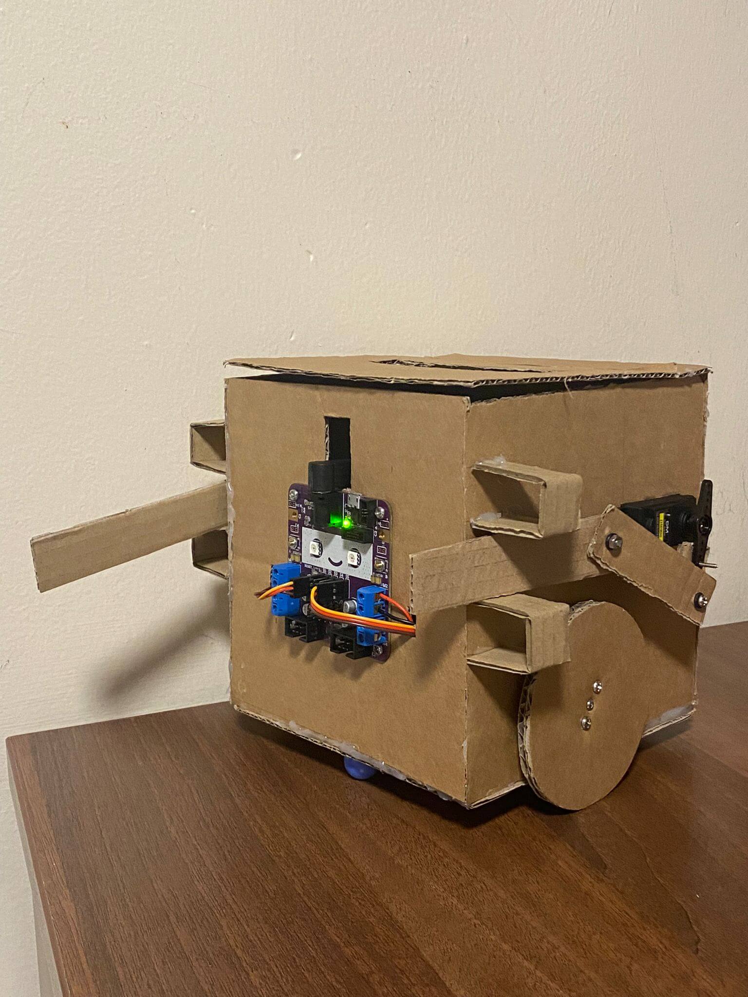 |
| Front | 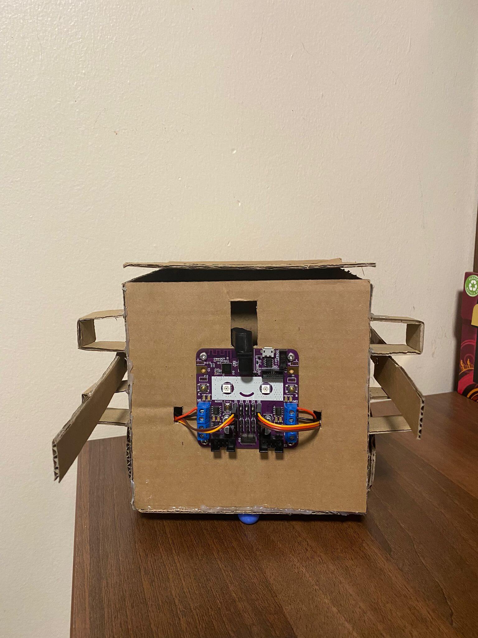 |
| Back | 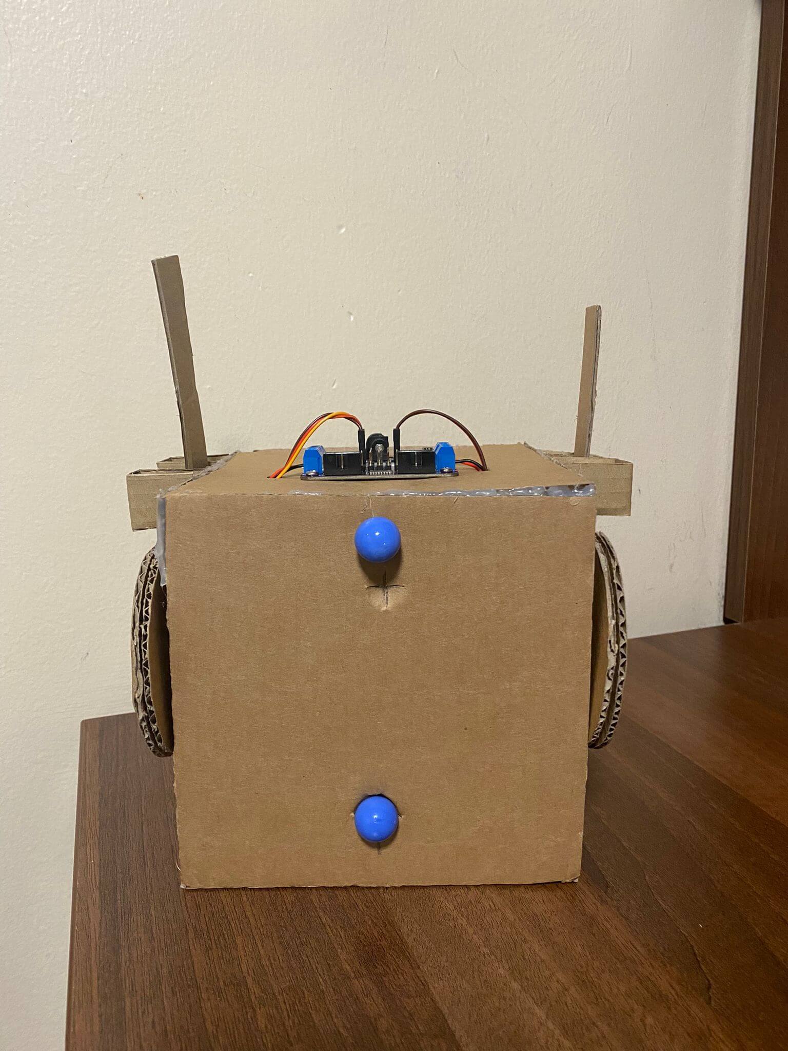 |
| Left | 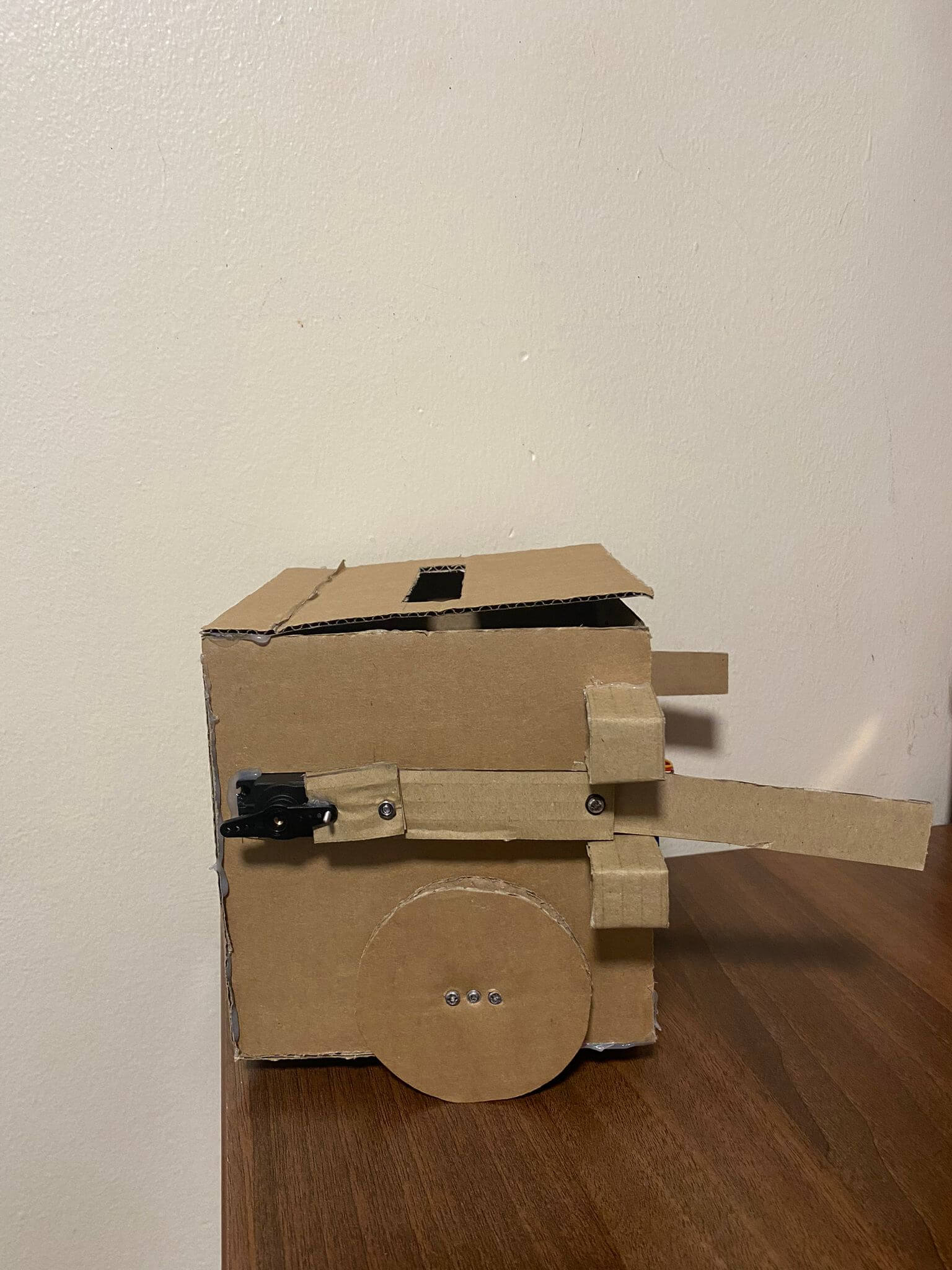 |
| Right | 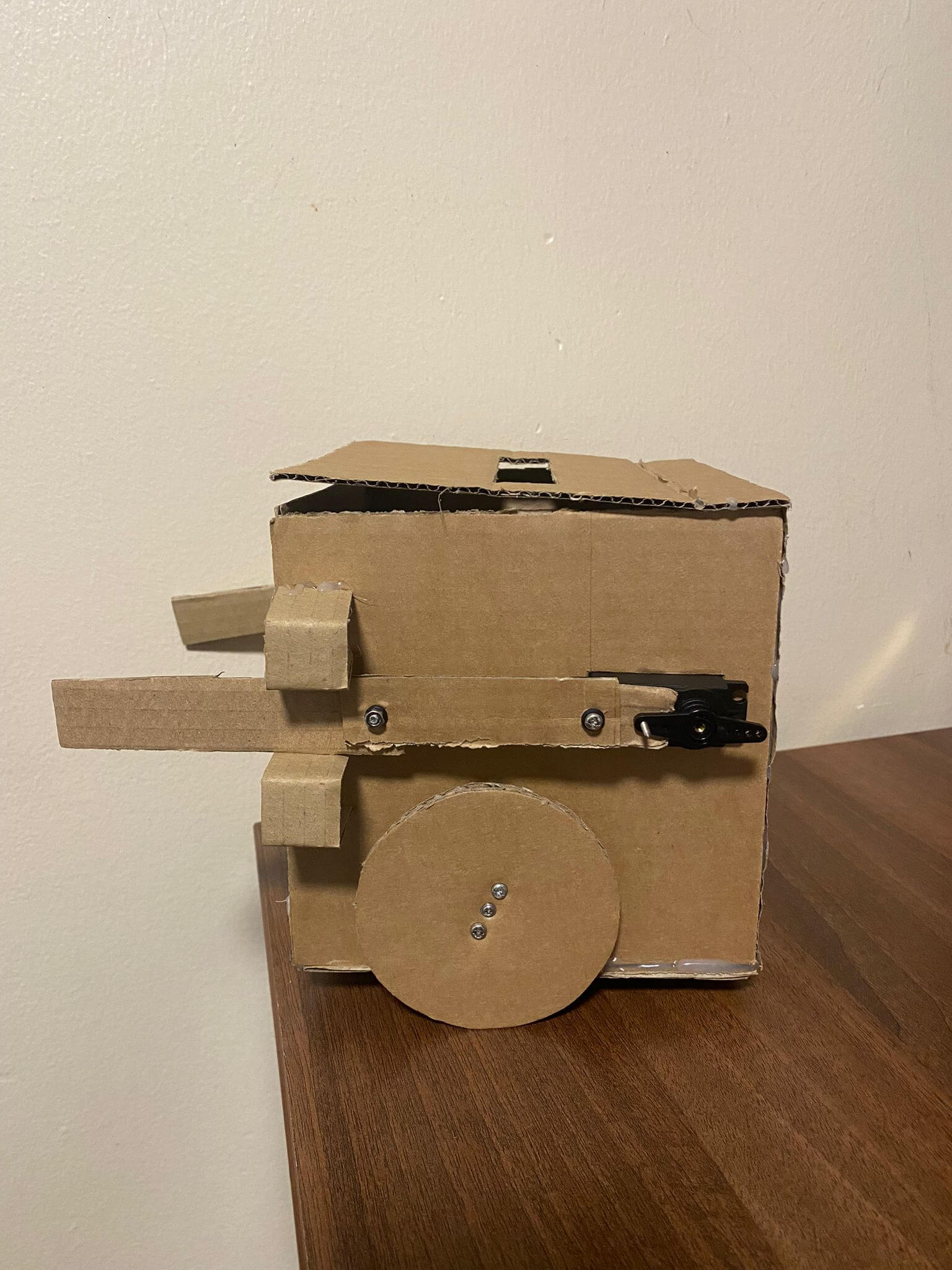 |
Tutorial
Template
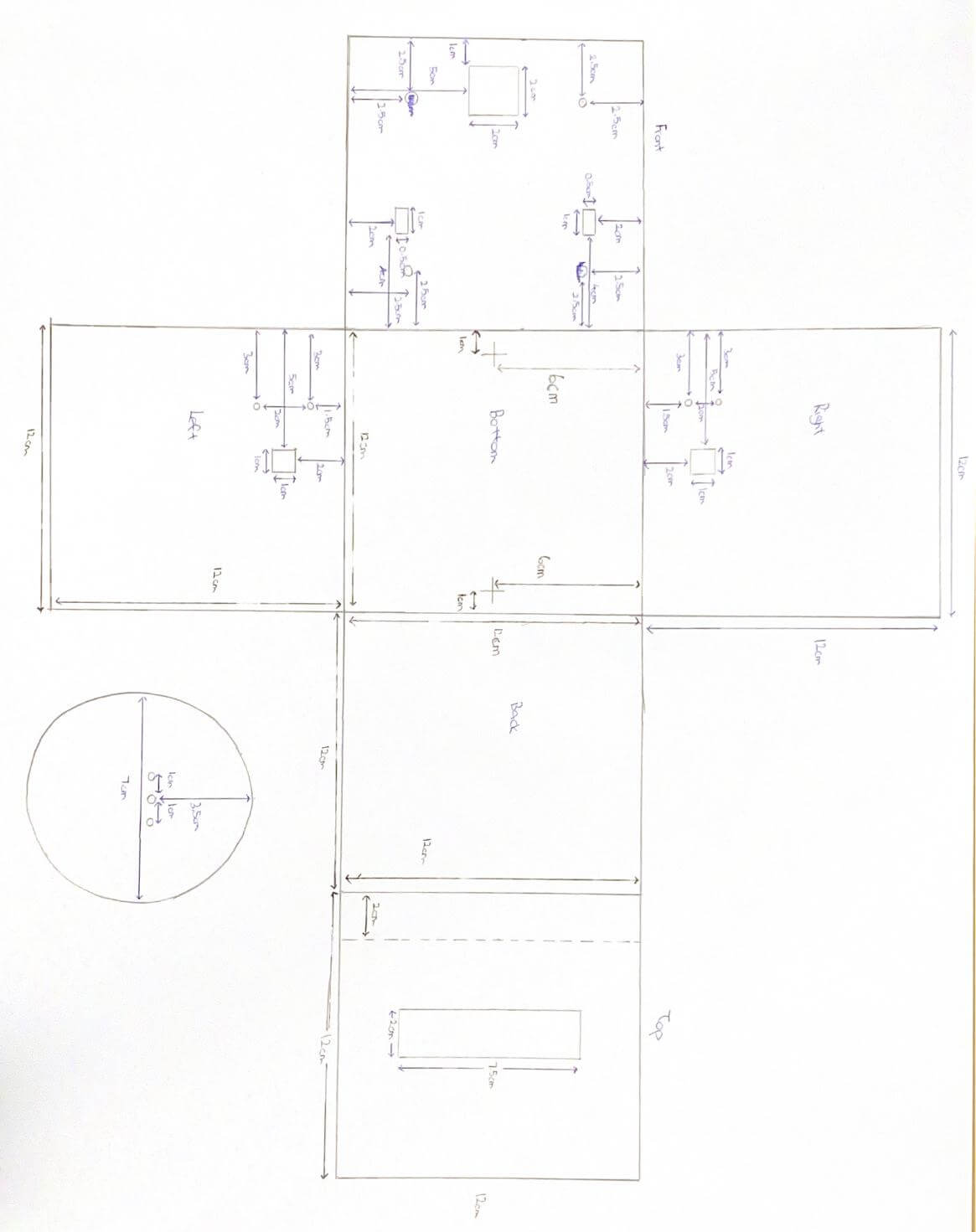
This is the core unit template
Video
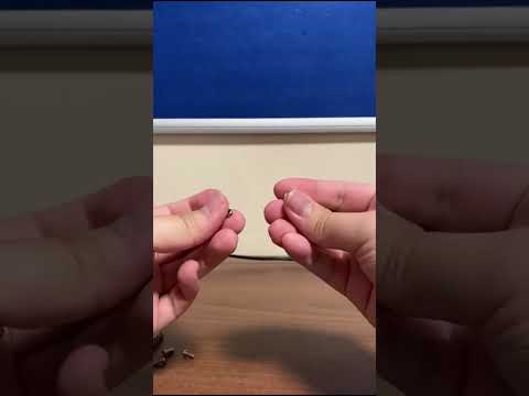
This is a step-by-step video showing how to build the core unit.
Step-by-Step Guide
Step 1: Align the chip with the 4 screw holes on the front piece. Screw it in with 4 short screws and bolts. Ensure that the charging port of the chip is right under the charging port cutout slot of the front piece.
Step 2: Fold the front, back, right, and left pieces 90 degrees upwards vertically. Glue the 4 corners, forming a cube with the top piece not glued.
Step 3: Fold the top piece along the dotted lines upwards and outwards. Glue the shorter end of the fold to the rest of the cupboard structure, making the longer end of the fold act as a flap to open and close.
Step 4: Place a motor into the inside of the cube and position it on the right piece such that the white protruding end of the motor is sticking out the 1cm X 1cm hole on the other side and the two holes on the motor is aligned with the two screw holes on the right piece.
Step 5: Repeat step 4 on the left piece. Bear in mind that the left piece is a mirror of the right piece.
Step 6: Attach the wheels onto the white protruding end of the motor that is sticking out of the cube, on both the left and right pieces respectively.
Step 7: Bring the red and black wires of both motors through the 1cm X 0.5cm holes of the front piece respectively. Connect the red wires of both the motors to the topmost connection port on their respective sides. Connect the black wires of both motors to the second topmost connection port on their respective side.
Step 8: Place the battery pack inside the cube. Pass the wire through the 2cm X 2cm hole of the front piece and connect to the power port of the chip.
Step 9: Glue 1 marble each on the 2 cross marked spots under the bottom piece.